Views: 0 Author: Site Editor Publish Time: 2026-11-13 Origin: Site
Heat generated by underground power cables must dissipate through the surrounding native soil to prevent dielectric breakdown. When thermal energy cannot escape efficiently, conductor temperatures rise rapidly. This degrades the cross-linked polyethylene or ethylene propylene rubber insulation over time. The operational consequences of undersized or poorly planned cable systems are severe. Operators face strict derating penalties, elevated power losses, and the risk of catastrophic failures caused by thermal runaway. This article establishes a comprehensive framework for calculating, measuring, and mitigating the influence of the surrounding subterranean environment. We define the exact mechanisms dictating thermal transfer. You will learn how to evaluate site-specific conditions, apply engineered backfills, and ensure reliable, long-term power delivery across your infrastructure.
The Moisture Link: Soil thermal resistivity is dynamic, directly tied to moisture content; assuming static values leads to significant overestimation of ampacity.
The Thermal Runaway Risk: Why ignoring soil drying-out effects can trigger a self-reinforcing cycle of heat generation and insulation failure.
Standardization vs. Reality: Comparing industry standard assumptions (e.g., IEC 60287) against site-specific field measurements.
Mitigation Strategy: The critical role of engineered thermal backfill in stabilizing ampacity regardless of ambient soil conditions.
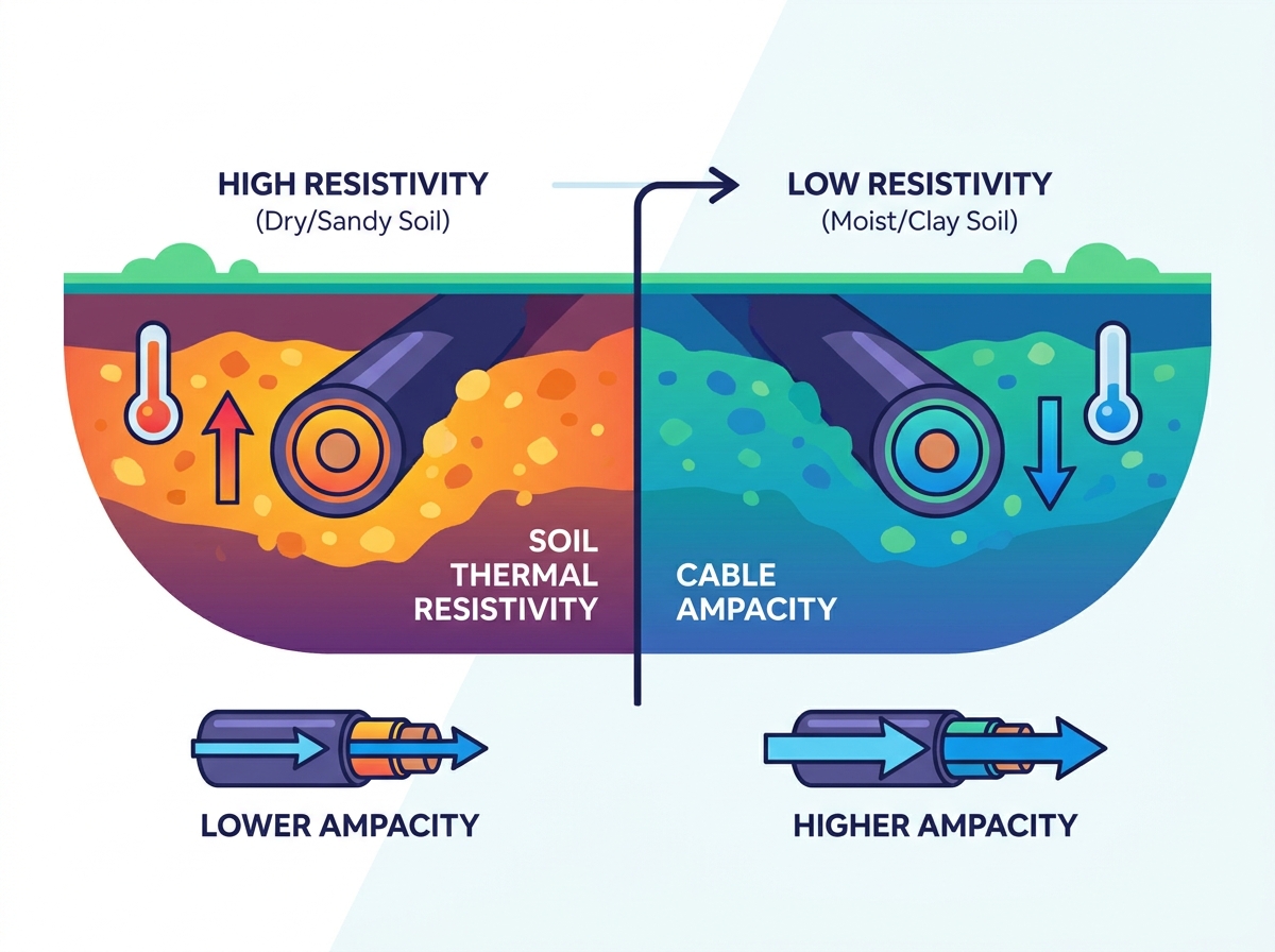
Soil thermal resistivity, commonly referred to as Rho (ρ), measures a material's resistance to heat flow. We express this value in degrees Celsius centimeter per watt (°C·cm/W). It represents the exact inverse of thermal conductivity. A low Rho value indicates that heat moves easily through the medium. A high Rho value means the material acts as an insulator, trapping heat. In underground power transmission, the surrounding earth serves as the primary heat sink. The native soil must absorb and dissipate the thermal energy generated by electrical losses within the cable conductor. When you evaluate soil thermal resistivity cable ampacity, you are essentially determining the thermal efficiency of the entire circuit.
Heat moves outward from the cable conductor through a series of thermal resistances. It passes through the insulation, the metallic shield, the outer jacket, and any protective bedding materials. Finally, the heat enters the surrounding native soil. Conduction serves as the primary mode of heat transfer in this environment. The efficiency of this conduction depends entirely on the physical contact between soil particles. Solid mineral grains conduct heat well. Air and water fill the void spaces between these grains. Water conducts heat moderately well, while air acts as a poor conductor. Therefore, the ratio of solids, water, and air dictates the overall thermal transfer rate.
Engineers rely on established standards like IEC 60287 and the Neher-McGrath method to determine safe operating currents. These frameworks calculate ampacity by balancing heat generation against heat dissipation. The equations factor in conductor resistance, dielectric losses, and ambient earth temperature. The soil thermal resistivity cable ampacity relationship remains the most sensitive variable in these calculations. Standard formulas treat the subterranean environment as a series of thermal resistors. The soil represents the largest and most variable resistor in the entire circuit. Accurately quantifying this resistance ensures the cable operates within its designed temperature limits, typically 90°C for modern XLPE insulation.
Small changes in resistivity values lead to non-linear drops in permissible current-carrying capacity. You cannot assume a linear correlation between soil properties and cable performance. An increase in Rho from 90 °C·cm/W to 120 °C·cm/W might force a 15% reduction in allowable ampacity. If the value spikes to 200 °C·cm/W due to extreme drying, the ampacity could plummet by more than 30%. This sensitivity requires precise data input during the design phase. Relying on assumed values often results in undersized conductors. Undersized conductors run hotter, accelerating insulation aging and increasing the likelihood of premature system failure.
Moisture content acts as the primary dynamic variable controlling thermal behavior. Water bridges the gaps between solid soil particles, facilitating efficient heat transfer. However, heat generated by the cable alters this moisture distribution. Thermally driven moisture migration occurs when water molecules vaporize near the hot cable interface. This vapor moves outward toward cooler soil regions, where it condenses. This continuous process creates a high-resistivity dry zone immediately surrounding the cable. As the dry zone expands, the effective thermal resistance of the installation increases rapidly. This phenomenon fundamentally alters the operating conditions of the power circuit.
Baseline thermal performance depends heavily on particle size distribution and mineralogy. Quartz possesses exceptionally high thermal conductivity. Soils with high quartz sand content generally exhibit lower thermal resistivity. Conversely, organic soils, peat, and certain clays trap air and resist heat flow. Dry density also plays a critical role. Highly compacted soils have less void space. Tightly packed particles provide more direct contact points for heat conduction. Poorly compacted trench backfill introduces excessive air voids, drastically increasing the local Rho value. Proper mechanical compaction during installation remains non-negotiable for achieving design thermal targets.
Subterranean environments fluctuate constantly. Seasonal water table variations directly impact long-term thermal resistance values. During wet seasons, high water tables saturate the soil, keeping resistivity low. Extended droughts lower the water table, draining the upper soil layers. Surface evaporation rates and local rainfall patterns further influence moisture content at standard cable burial depths. Shallow installations experience more aggressive moisture swings. Engineers must account for the worst-case environmental scenario. Designing a system based on springtime moisture levels guarantees overheating during late summer dry spells.
Inaccurate soil data forces severe operational penalties upon infrastructure projects. When engineers discover high resistivity values late in the design process, they must derate the cable system. Derating means reducing the maximum allowable current to prevent overheating. To meet the original power transmission targets, the project requires larger cable cross-sections or entirely new parallel circuits. Upgrading from a 500 kcmil conductor to a 750 kcmil conductor drastically increases material volume requirements. It also requires larger conduits, wider trenches, and heavier pulling equipment. These cascading modifications disrupt planning and extend construction timelines.
Ignoring soil drying-out effects invites catastrophic failure. Thermal runaway operates as a vicious, self-reinforcing cycle. It begins when localized cable heating exceeds the soil's ability to dissipate energy. The excess heat drives moisture away from the cable jacket. This moisture loss increases the surrounding soil resistivity. Higher resistivity reduces heat dissipation further, causing the cable temperature to spike again. This secondary temperature rise drives away even more moisture, expanding the dry zone. The cycle accelerates rapidly. Within a matter of days or weeks, the conductor temperature exceeds the insulation's thermal limits. The dielectric material melts or degrades, resulting in a direct short circuit.
A comprehensive geotechnical investigation requires initial effort. However, this investment pales in comparison to the long-term operational risks of premature cable failure. Splicing a faulted high-voltage underground line incurs massive operational liabilities in labor, materials, and specialized equipment. Unplanned outages trigger regulatory scrutiny and disrupt downstream operations. Comparing the minimal effort of thermal surveys against these massive operational liabilities makes the decision clear. Site-specific data acquisition serves as the most effective insurance policy for underground transmission infrastructure.
Accurate evaluation demands rigorous field testing. You cannot rely on historical data, generic tables, or regional typical values. These shortcuts ignore site-specific hydrology and localized soil variations. The industry standard for in-situ measurement is ASTM D5334. This protocol utilizes a thermal needle probe inserted directly into the undisturbed earth. The probe contains a heating element and a temperature sensor. By applying a known constant heat source and measuring the temperature rise over time, engineers calculate the exact thermal resistivity of the native material. Field tests should occur at the exact proposed depth of the cable installation.
Field testing only provides a snapshot of current conditions. To understand long-term behavior, engineers must extract undisturbed soil samples for laboratory analysis. The laboratory environment allows technicians to construct a complete thermal dry-out curve. They measure the thermal resistivity of the sample at various controlled moisture contents, from fully saturated to completely bone-dry. This curve reveals the critical moisture content—the exact point where the soil transitions from a stable conductor to a thermal insulator. Understanding this threshold allows designers to predict how the trench will perform during severe droughts.
Establishing the final design value requires balancing conservative safety factors against project constraints. You should not blindly select the highest possible Rho value from the completely dry state, as this leads to massive over-engineering. Instead, analyze the dry-out curve alongside local hydrological data. Determine the lowest probable moisture content the soil will experience during the cable's operational lifespan. Select the corresponding Rho value from the laboratory curve. This data-driven framework ensures the system remains safe under worst-case conditions without incurring unnecessary material volume.
Comparison of Soil Thermal Resistivity Evaluation Methods | |||
Evaluation Method | Data Accuracy | Operational Impact | Primary Use Case |
|---|---|---|---|
Generic Standard Tables | Low | High Risk | Feasibility studies |
In-Situ Field Testing | Moderate | Moderate | Baseline verification |
Lab Dry-Out Curve | High | High Effort | Final design |
When native soils exhibit poor thermal properties, engineers replace them with engineered thermal backfill. These specialized materials maintain low thermal resistivity even when completely dry. Fluidized Thermal Backfill (FTB) represents the most common solution. FTB flows like a liquid during installation, filling all void spaces around the conduits. It cures into a solid, stable mass. The mix design typically incorporates specific ratios of sand, cement, fly ash, and water. By controlling the exact aggregate gradation, FTB achieves high density and excellent heat transfer characteristics. It stabilizes the ampacity rating regardless of ambient soil drying.
While FTB provides permanent thermal stabilization, it introduces maintenance challenges. Cementitious backfills harden significantly over time. You must evaluate the trade-offs between thermal performance and future excavability. If maintenance crews need to access the cables or splice vaults, high-strength concrete backfills require heavy demolition equipment. To mitigate this, engineers specify low-strength, excavatable FTB mixes. These mixes cap the compressive strength at around 100 to 200 psi. This ensures the material remains soft enough for manual removal or hydro-excavation while still delivering the required thermal conductivity.
The physical arrangement of the underground circuit drastically impacts the localized thermal bottleneck. Depth of burial plays a dual role. Deeper installations protect cables from surface damage and extreme temperature swings. However, deeper soils often possess different thermal characteristics and restrict heat flow to the surface. Cable grouping also compounds thermal resistance. Placing multiple circuits in a single narrow trench forces them to share the same heat sink. The thermal fields overlap, increasing the ambient temperature for all cables. Spreading the phases apart or increasing the distance between parallel circuits reduces this mutual heating effect.
Integration begins during the earliest geotechnical phases. Conduct a thorough desktop study of local geological maps and historical bore logs. Identify potential high-resistivity zones, such as areas with deep organic peat deposits or loose, poorly graded sands. Perform preliminary field resistivity tests along the proposed route. Use this data to optimize the alignment. Routing the trench through favorable thermal environments reduces the need for imported backfills. Document all soil strata variations to inform the subsequent modeling phases.
Transition from raw data to numerical simulation. Utilize Finite Element Analysis (FEA) software to model complex multi-circuit thermal interactions. FEA tools allow engineers to input the specific laboratory dry-out curves mapped during the testing phase. Construct a 2D or 3D model of the trench cross-section. Apply the worst-case moisture scenarios and maximum anticipated load currents. The simulation visualizes the heat flux moving through the engineered backfill and into the native soil. This predictive modeling validates the proposed cable sizing and trench geometry before any physical construction begins.
Design models require real-world validation. Establish post-installation monitoring protocols for all critical high-voltage infrastructure. Install Distributed Temperature Sensing fiber optic cables directly alongside the power conductors. These systems use laser pulses to measure temperature variations along the entire length of the circuit in real-time. Monitor the thermal response during initial load testing and early operational phases. Compare the live temperature data against the FEA predictions. If localized hot spots emerge, the system alerts operators immediately. This allows for proactive load management before thermal runaway damages the insulation.
Accurate subterranean data forms the foundational requirement for any robust, compliant underground transmission system. The physical properties of the earth dictate how efficiently heat escapes from the conductor. Ignoring these variables leads directly to derating penalties, accelerated insulation degradation, and catastrophic thermal runaway. The shift from relying on standardized, optimistic assumptions to executing site-specific engineering serves as the primary driver of project longevity. By measuring actual field conditions and deploying engineered thermal backfills, operators guarantee operational safety. Implement these next steps:
Execute ASTM D5334 field testing during the Front-End Engineering Design phase.
Commission laboratory thermal dry-out curves for all native soil samples.
Specify excavatable Fluidized Thermal Backfill for high-resistivity installation zones.
Deploy real-time Distributed Temperature Sensing systems on critical high-voltage circuits.
A: The surrounding earth acts as the primary heat sink for underground cables. Soil thermal resistivity dictates how fast heat dissipates from the conductor. Because the soil represents the largest thermal resistor in the system, even minor fluctuations in its resistivity cause massive, non-linear reductions in allowable ampacity. Inaccurate values lead directly to undersized cables and overheating.
A: Water conducts heat significantly better than air. High moisture content bridges the gaps between soil particles, lowering thermal resistivity and allowing the cable to carry more current safely. When soil dries out, air replaces the water. This increases thermal resistance, traps heat, and drastically reduces the cable's effective ampacity.
A: They are exact mathematical inverses. Thermal resistivity (Rho) measures a material's resistance to heat flow, expressed in °C·cm/W. Thermal conductivity measures a material's ability to transfer heat, expressed in W/(m·K). Cable engineers primarily use resistivity (Rho) because standard ampacity formulas treat the soil as a thermal resistor in a series circuit.
A: You should never rely solely on standard table values for final engineering designs. Generic tables ignore local hydrology, compaction levels, and mineralogy. Site-specific field testing (ASTM D5334) and laboratory dry-out curves are mandatory to ensure accurate ampacity calculations, prevent thermal runaway, and avoid costly post-installation derating.
A: Engineered thermal backfill, like Fluidized Thermal Backfill (FTB), utilizes a specific mix of sand, cement, and fly ash to eliminate air voids. It maintains a very low thermal resistivity even when completely devoid of moisture. By providing a stable, highly conductive heat path, it prevents the localized heat buildup that triggers thermal runaway.
A: Testing must occur during the Front-End Engineering Design (FEED) or early geotechnical phase. Gathering this data before finalizing cable sizes and trench geometries prevents costly redesigns. Attempting post-facto corrections after discovering poor soil conditions during construction results in severe schedule overruns and project delays.