Views: 0 Author: Site Editor Publish Time: 2026-11-13 Origin: Site
Medium-voltage single-core cables experience continuous electromagnetic induction during operation. Alternating current flowing through the main conductor generates a radial magnetic field. This field intersects the metallic sheath surrounding the insulation, inducing a longitudinal voltage along the screen. You face a strict technical conflict here. You must minimize sheath circulating currents to maximize cable ampacity while preventing hazardous induced sheath voltages from endangering personnel. The choice of MV cable screen bonding directly impacts project viability. Selecting the wrong configuration forces severe cable derating. It can also require auxiliary protective components or compromise long-term asset reliability. This guide provides a definitive decision-support framework. Project managers and site engineers will learn how to select the optimal bonding strategy based on installation lengths, load profiles, and safety standards.
Circulating Current vs. Safety: Both-end bonding eliminates induced voltage hazards but forces derating due to circulating currents; single-point bonding maximizes ampacity but introduces voltage rise risks over distance.
The Distance Variable: Define the critical threshold (usually 300–500m) where induced sheath voltages in single-point systems exceed safe touch-potential limits, necessitating cross-bonding or solid grounding.
System Integrity: Highlight that shielding effectiveness for fault current return is heavily dependent on the bonding configuration chosen.
Economic Strategy: Compare the upfront capital expenditure of auxiliary components (SVLs, link boxes) against the long-term operational loss of derated cable capacity.
Alternating current in the main conductor creates an axial electromagnetic field. This magnetic flux links with the metallic screen or sheath. According to Faraday’s Law of Induction, this changing magnetic field induces an electromotive force (EMF) along the sheath. The magnitude of this induced voltage depends on the conductor current, system frequency, cable spacing, and parallel run length. Wider cable spacing increases the mutual inductance between the conductor and the sheath. Flat formation duct banks generate significantly higher induced voltages compared to tight trefoil arrangements. You must calculate these values accurately to ensure compliance with touch-potential safety limits before pulling any cable.
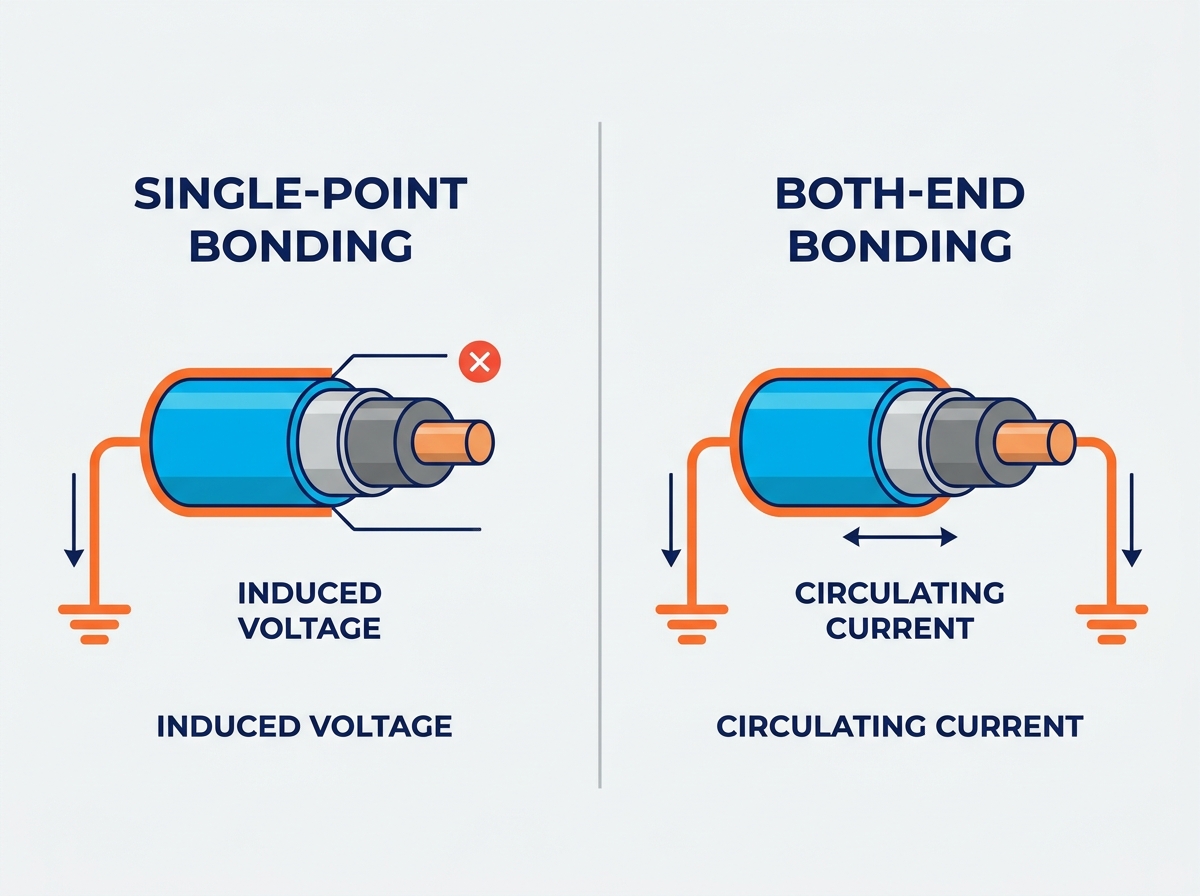
Grounding the cable screen at both ends creates a closed electrical circuit. The induced EMF drives a circulating current through this loop. The current travels down the cable sheath and returns through the ground path. The magnitude of this circulating current depends entirely on the induced voltage and the total loop impedance. Sheath resistance dictates the severity of this current. Copper wire screens possess very low resistance. If you ground both ends of a copper wire screen, the circulating current can approach the magnitude of the phase current itself. This circulating current generates resistive heating within the sheath. This additional heat source directly reduces the thermal capacity available for the main conductor.
Leaving one end of the cable screen isolated prevents the formation of a closed loop. Without a complete circuit, circulating currents cannot flow. This completely eliminates sheath heating losses. However, the induced EMF still exists. It manifests as a standing voltage at the ungrounded end of the cable. This potential difference scales linearly with the length of the cable run and the load current. A 100-meter cable carrying 400 amps might show 15 volts at the isolated end. A 1000-meter run under the exact same load could easily exceed 150 volts. This creates severe safety hazards for personnel and applies continuous dielectric stress on the outer cable jacket.
Bonding configurations dictate how zero-sequence currents behave during a ground fault. An asymmetric fault generates massive return currents. In a both-end bonded system, the continuous sheath provides a low-impedance return path back to the source. This minimizes the rise-of-earth-potential (ROEP) at the fault location. Single-point bonded systems lack this continuous metallic return path. Fault currents must return entirely through the surrounding earth or parallel ground continuity conductors (GCC). This increases the ROEP and causes dangerous step and touch potentials around the fault site. You must size the GCC appropriately to handle the full fault duty without melting.
Single-point bonding works best when maximizing cable ampacity is the primary goal. Short underground runs are ideal candidates. Facilities with limited trench space often require cables to operate at their maximum thermal limit. Retrofit scenarios also benefit heavily from this approach. Upgrading an existing duct bank with larger cables might exceed thermal dissipation limits if circulating currents are present. Eliminating these sheath losses allows you to push more power through the same physical infrastructure. Substations with short feeder connections and wind farm collector arrays frequently utilize single-point bonding to optimize conductor sizing and reduce copper costs.
The immediate operational benefit is the complete elimination of sheath circulating current losses. This optimizes the full current-carrying capacity of the cable. Standard IEC 60287 calculations show significant ampacity improvements when sheath losses drop to zero. Cables run cooler under normal load conditions. This extends the lifespan of the cross-linked polyethylene (XLPE) or ethylene propylene rubber (EPR) insulation. Lower operating temperatures reduce thermal degradation over the 30-year lifecycle of the asset. System efficiency improves because energy is not wasted heating the surrounding soil or concrete duct bank.
Single-point systems introduce specific operational hazards. Induced voltages pose severe risks to maintenance personnel. Even during normal operation, the isolated end carries a standing voltage. Fault conditions or high-load switching transients cause massive voltage spikes. These spikes can easily exceed safe touch-potential limits. The outer cable jacket also experiences continuous dielectric stress. The voltage difference between the grounded soil and the energized sheath stresses the PVC or PE oversheath. If the induced voltage exceeds the jacket's withstand rating, electrical breakdown occurs. This leads to jacket punctures, moisture ingress, and rapid screen corrosion.
Field engineers deploy Sheath Voltage Limiters (SVLs) to manage these risks. SVLs connect between the isolated screen end and the local ground grid. During normal operation, the SVL acts as an insulator. It maintains the single-point isolation and prevents circulating currents. When a transient surge occurs, the SVL conducts. It clamps the overvoltage to a safe level, protecting the cable jacket from dielectric breakdown. Once the transient passes, the SVL returns to its high-impedance state. Proper SVL installation requires strict adherence to the following field steps:
Verify the maximum expected fault current at the specific installation node.
Calculate the power-frequency overvoltage during a worst-case asymmetric fault.
Select an SVL continuous operating voltage (COV) that exceeds the calculated overvoltage to prevent thermal runaway.
Mount the SVL inside a sealed, IP68-rated link box to prevent moisture ingress during vault flooding.
Connect the grounding cable using constant-force springs or heavy-duty compression lugs to ensure low contact resistance.
Both-end bonding prioritizes system simplicity and robust fault path conductivity. It is the standard choice for shorter distances where circulating current losses remain within acceptable heat margins. Industrial plants and commercial facilities heavily favor this method. The design requires no specialized link boxes or SVLs. Installation is straightforward for electrical contractors. The continuous screen provides excellent electromagnetic shielding against external interference. It also guarantees a reliable, low-impedance return path for ground faults. When the cable ampacity requirement is well below the physical conductor limit, both-end bonding is the safest and most reliable choice.
Circulating currents generate heat. This heat reduces the effective current-carrying capacity of the cable. You must account for this ampacity penalty during the design phase. IEC 60287 standards mandate strict derating factors for both-end bonded systems. The magnitude of the penalty depends heavily on the cable formation. Flat formations induce higher and unbalanced voltages across the three phases. This leads to severe circulating currents in the outer cables. Trefoil formations keep the phases equidistant. This balances the magnetic fields and significantly reduces induced voltages. Consequently, trefoil installations suffer a much lower ampacity penalty than flat installations.
Both-end bonding inherently protects the outer cable jacket. Because the sheath is grounded at multiple points, no high standing voltages develop. The voltage across the jacket remains near zero under normal conditions. This eliminates the risk of dielectric breakdown. Moisture ingress due to jacket punctures becomes highly unlikely. The absence of SVLs removes a potential point of failure. SVLs degrade over time or fail short after multiple surge events. Solidly bonded systems bypass this maintenance burden entirely. The overall physical reliability of the cable installation increases, requiring fewer man-hours for lifecycle inspections.
Solidly grounding both ends creates a massive ground loop. Stray ground currents from other facility equipment can enter the cable screen. These stray currents add to the magnetically induced circulating currents. This loop causes severe electromagnetic interference (EMI). Sensitive secondary monitoring circuits running parallel to the power cables often suffer from this interference. Control signals degrade. Instrumentation readings fluctuate. You must carefully route communication cables away from both-end bonded power runs. Shielding control cables and utilizing twisted pair configurations helps mitigate this ground loop interference in heavy industrial environments.
Selecting the correct bonding method requires balancing distance, load, and safety limits. Induced voltage limits dictate the maximum length for single-point systems. Most utility standards restrict normal operating sheath voltage to 65V for personnel safety. Some industrial standards allow up to 150V if access is strictly controlled in locked vaults. Load profile analysis determines if the ampacity penalty of both-end bonding is acceptable. If the required load pushes the cable past its thermal limit, single-point bonding becomes mandatory.
Bonding Method | Ampacity Rating | Max Distance (Typical) | Maintenance Need | Safety Profile |
|---|---|---|---|---|
Both-End Bonding | Derated (High sheath losses) | Unlimited (Thermally constrained) | Low (No SVLs to inspect) | High (Zero standing voltage) |
Single-Point Bonding | Maximum (Zero circulating current) | 300m - 500m (Voltage constrained) | Medium (SVL testing required) | Moderate (Standing voltage present) |
Cross-Bonding | Maximum (Balanced currents cancel out) | Long Transmission (>1000m) | High (Link boxes, SVLs, joint bays) | High (Voltages kept within limits) |
Design choices made today limit future operational flexibility. Installing a both-end bonded system at 90% thermal capacity leaves no room for expansion. If facility loads increase, the cables will overheat. Upgrading to a single-point system later requires expensive underground modifications. You must excavate splice vaults, install link boxes, and fit SVLs. Conversely, designing a single-point system from day one provides maximum thermal headroom. You must evaluate the projected 20-year load growth before finalizing the bonding configuration to avoid stranded assets.
Maintenance requirements differ drastically between configurations. Solid bonding requires almost zero ongoing maintenance. Visual inspections of the grounding lugs suffice. Single-point systems demand rigorous testing. SVLs degrade after absorbing transient surges. Maintenance teams must perform regular DC leakage current tests on SVLs during scheduled outages. Link boxes require inspection for water ingress and corrosion. If an SVL fails short, the system inadvertently becomes both-end bonded. This introduces circulating currents that the cable was not thermally designed to handle, leading to rapid overheating and insulation failure.
When cable runs exceed the safe voltage limits of single-point bonding, you must pivot. Cross-bonding is the standard transition for long, high-load transmission segments. Cross-bonding divides the cable route into three equal minor sections. The sheaths are transposed at link boxes. The induced voltages in the three sections cancel each other out. This eliminates circulating currents while keeping standing voltages near zero. However, cross-bonding requires significant capital expenditure. It involves complex joint bays, specialized link boxes, and precise phase transposition engineering.
Safety drives every bonding decision. Touch-potential protection is non-negotiable. Link boxes in single-point systems must feature robust locking mechanisms. Only qualified personnel should access these vaults. Effective grounding at transition points ensures fault currents dissipate safely into the earth. Ground grid resistance must measure below specified limits, typically under 1 ohm for substations. You must specify insulated concentric bonding leads to connect the cable screen to the link box. This prevents accidental grounding of the sheath before it reaches the SVL.
Strict adherence to international standards prevents catastrophic failures. IEEE 575 provides comprehensive guidelines for applying link boxes and SVLs. It details the calculation methods for induced voltages and circulating currents. IEC 60287 governs the thermal rating calculations. It dictates exactly how much to derate a cable based on sheath losses. Local utility regulations often impose stricter limits on touch potentials than international standards. Compliance requires submitting detailed sheath voltage calculations during the design approval phase before any trenching begins.
Improper installation ruins the best engineering designs. Poor bonding connections lead to high contact resistance. This causes localized heating and premature jacket failure. Sheath corrosion is a common failure mode in improperly sealed link boxes. Water ingress bridges the isolation gap, creating unintended ground loops. Quality assurance teams must conduct Ductor testing (micro-ohmmeter testing) on all mechanical connections. Jacket integrity tests using a 10kV DC overvoltage must occur after backfilling. This ensures no mechanical damage compromised the isolation during the cable pull.
Maintaining shield continuity is critical for fault clearing. Impedance discontinuities disrupt the zero-sequence return path. This delays relay operation and increases fault damage. Mechanical connections between the copper tape or wire screen and the bonding lead must be flawless. Installers use specialized constant-force springs or compression lugs. Soldering is generally avoided due to its vulnerability to fault-current melting. The grounding buses inside link boxes must handle the full prospective short-circuit current without deforming or breaking.
Run a load flow simulation using power systems software to determine the exact ampacity requirements and thermal constraints for your specific cable route.
Calculate the maximum induced sheath voltage under both normal operating loads and worst-case asymmetric fault conditions to verify touch-potential safety.
Specify IP68-rated link boxes and properly sized Sheath Voltage Limiters (SVLs) in your procurement documents if single-point bonding is required.
Mandate post-installation DC overvoltage testing on the outer cable jacket to verify isolation integrity before energizing the system.
A: The maximum distance depends entirely on the load current and mutual inductance, but typically falls between 300 and 500 meters. Utility standards usually restrict normal operating standing voltages to 65V for personnel safety. Once the calculated induced voltage exceeds this threshold, you must transition to cross-bonding or solid grounding.
A: Both-end bonding eliminates standing voltages on the jacket, removing touch-potential hazards during normal operation. It also provides a continuous, low-impedance return path for ground faults. However, the resulting circulating currents generate significant heat, which degrades insulation if the cable is not properly derated.
A: Circulating currents flow through the metallic sheath and generate I²R resistive heating. This additional heat source raises the overall temperature of the cable. To prevent the core insulation from exceeding its thermal limit, the current carried by the main conductor must be reduced.
A: SVLs are transient overvoltage protection devices used in single-point bonded systems. They connect the isolated cable screen to the ground. Under normal conditions, they act as insulators. During switching surges or ground faults, they conduct to clamp dangerous voltage spikes, protecting the cable jacket from dielectric breakdown.
A: Mixing methods requires careful engineering and is generally avoided without specific transition points. Segmented configurations require link boxes and solid grounding points to isolate the different bonding zones. Inconsistent design leads to unpredictable circulating currents, localized overheating, and dangerous touch potentials at transition joints.
A: Cross-bonding divides a long cable route into three equal sections and transposes the sheaths between phases. This cancels out the induced voltages, eliminating circulating currents while keeping standing voltages near zero. It is a high-capital alternative used primarily for long transmission runs where single-point limits are exceeded.
A: Induced voltages create a potential difference between the metallic screen and the surrounding grounded earth. This places continuous electrical stress on the PVC or PE outer jacket. If the voltage exceeds the jacket's dielectric withstand capability, it causes punctures, leading to moisture ingress and rapid sheath corrosion.