Views: 0 Author: Site Editor Publish Time: 2026-11-13 Origin: Site
Electrical engineers face a persistent dilemma when routing single-core power cables. You must balance ampacity limits, mechanical force endurance, and physical tray footprint. The arrangement dictates system impedance, loss factors, and short-circuit performance. It is never just a routing preference. The two primary installation methods are trefoil (triangular) and flat (side-by-side) configurations. Choosing between a trefoil vs flat cable formation requires evaluating electromagnetic fields and thermal dynamics. This guide delivers an objective framework for selecting the optimal layout based on site conditions. We cover flux cancellation mechanics, mechanical stress management, and tray space optimization. By applying these physical principles, you ensure long-term reliability across high-voltage and medium-voltage networks.
Ampacity Optimization: Trefoil generally offers better flux cancellation, while flat formations can be optimized through specific spacing to manage thermal constraints.
Short-Circuit Resilience: Trefoil provides superior mechanical stability during fault conditions, significantly reducing stresses on cable cleats.
Installation Constraints: Flat formations often simplify cable tray/trench space allocation but may increase eddy current losses in metallic components.
Decision Framework: Selecting the right formation requires balancing electromagnetic field (EMF) impacts, cable tray mechanical load capacity, and site-specific thermal resistivity.
Three-phase power systems operate with a 120-degree electrical phase shift between conductors. This phase shift creates distinct, alternating magnetic fields around each individual cable. When you place these cables in close proximity, their magnetic fields interact continuously. The physical geometry of the cable arrangement directly dictates the nature of this interaction. If the physical arrangement mirrors the electrical phase shift perfectly, the magnetic fields oppose one another. This opposition leads to flux cancellation. Effective flux cancellation minimizes the external magnetic field surrounding the cable group. It reduces induced voltages in nearby metallic structures like tray rungs and support brackets. It also lowers the circulating currents within the cable screens themselves. Field engineers rely on this cancellation to prevent localized heating in adjacent steelwork. Without proper cancellation, you risk inducing dangerous touch voltages on exposed metal surfaces. You must account for these interactions during the initial routing design phase to prevent costly rework.
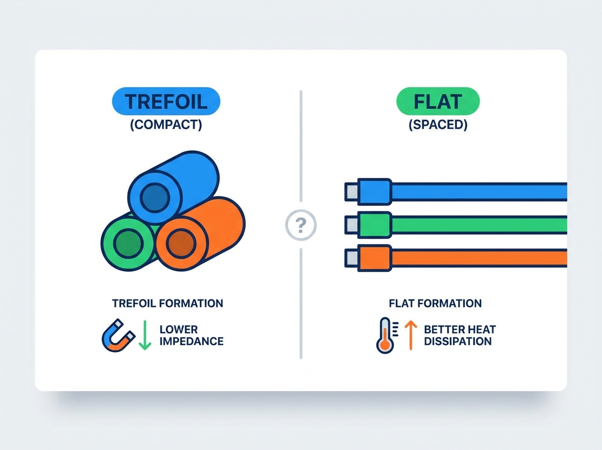
A trefoil formation arranges three single-core cables in an equilateral triangle. This physical symmetry perfectly complements the 120-degree electrical phase shift. The distance between the center of any two cables remains identical throughout the run. As a result, the vectorial sum of the magnetic flux approaches zero. This near-perfect magnetic field cancellation provides massive operational advantages. It drastically reduces induced circulating currents in the metallic screens. Lower circulating currents mean less resistive heating within the screen material. This reduction in heat generation protects the cross-linked polyethylene (XLPE) or ethylene propylene rubber (EPR) insulation from thermal degradation. Trefoil arrangements effectively contain the electromagnetic field within the immediate vicinity of the cables. This containment protects adjacent sensitive electronic equipment, such as SCADA communication lines, from magnetic interference. You maintain a clean electromagnetic environment across the facility. Maintaining this perfect equilateral triangle over long distances requires precise cleating and careful tensioning during the cable pull.
A flat formation places the three cables side-by-side in a single horizontal or vertical plane. This geometry inherently lacks the physical symmetry of a trefoil layout. The middle phase sits closer to the two outer phases than the outer phases sit to each other. This unequal spacing creates an unbalanced magnetic flux. The magnetic field cancellation is incomplete and heavily skewed. Consequently, the induced voltages in the metallic sheaths vary significantly across the three phases. The middle cable typically experiences the highest induced voltage. If the sheaths are bonded at both ends, this voltage drives substantial circulating currents. These currents generate localized heating, particularly in the center phase. You must account for this unbalanced thermal load when calculating the overall system ampacity. Field crews often measure higher operating temperatures on the center phase during routine infrared thermography inspections. To mitigate this, engineers sometimes transpose the phases at specific intervals along the route, physically swapping their positions to balance the impedance.
The benefits of trefoil formation rely entirely on the interaction of the magnetic fields from the bare conductors. Metallic armoring or separate magnetic conduits disrupt this interaction completely. If you place individual single-core cables inside separate steel conduits, the conduit absorbs and contains the magnetic field. The fields never interact in the space between the cables. Placing three steel conduits in a trefoil arrangement provides absolutely no flux cancellation benefits. The same limitation applies to single-core cables with individual steel wire armor (SWA). The armor acts as a magnetic shield around each core. The flux is neutralized locally within the armor, causing massive eddy current losses and rapid overheating. You should only use trefoil formations for unsheathed cables or cables with non-magnetic armoring like aluminum wire armor (AWA). Using SWA in single-core AC systems violates basic electrical design principles and leads to catastrophic insulation failure. Always verify the armor material before specifying a trefoil layout.
Ampacity depends heavily on how efficiently a cable system dissipates heat into the surrounding environment. Trefoil formations bundle the three cables tightly together. This tight grouping restricts airflow around the individual cores. The mutual heating effect between the cables is high. You must apply significant thermal grouping factors to derate the ampacity. Flat formations spread the cables out. If you introduce spacing between the cables in a flat layout—typically one cable diameter apart—convective cooling improves dramatically. This enhanced heat dissipation often allows for a higher ampacity rating compared to a bundled trefoil. However, you must balance this thermal advantage against proximity effect losses. The proximity effect alters the current distribution within the conductor itself. In flat formations, the unbalanced magnetic fields push the current toward the outer edges of the conductors. This increases the effective AC resistance of the cable. You must calculate both the thermal dissipation gains and the proximity effect losses to determine the true ampacity. IEC 60287 provides the standard formulas for these calculations, factoring in soil thermal resistivity for buried sections and ambient air temperatures for above-ground trays.
Evaluation Metric | Trefoil Formation | Flat Formation (Spaced) |
|---|---|---|
Magnetic Flux Cancellation | Excellent (near zero vector sum) | Poor (unbalanced, highest on middle phase) |
Thermal Dissipation | Lower (cables heat each other) | Higher (better airflow between cables) |
Short-Circuit Stability | High (acts as a structural truss) | Low (requires heavy lateral restraint) |
Space Requirement | Narrow and deep footprint | Wide and shallow footprint |
Eddy Current Losses in Tray | Minimal | Moderate to High |
During a short-circuit fault, cables experience massive electrodynamic forces. These forces attempt to violently repel the conductors from one another. The magnitude of this force is inversely proportional to the distance between the cable centers. Because trefoil formations pack the cables tightly, the initial repulsive forces are extremely high. However, the triangular geometry provides a distinct mechanical advantage. The trefoil arrangement acts as a natural structural truss. When bound by properly specified cable cleats, the cables brace against each other. The forces distribute evenly across the triangular bundle. Flat formations lack this mutual bracing. Fault forces simply push the cables apart in a linear direction. This places immense lateral stress on the cable cleats and the supporting tray structure. You must specify significantly stronger support infrastructure for flat formations in high-fault environments. IEC 61914 outlines the testing procedures for cable cleats, ensuring they can withstand these peak electromechanical stresses without yielding. You must calculate the peak short-circuit current and select cleats with a certified fault rating that exceeds your system parameters.
Unbalanced magnetic fields in flat formations induce eddy currents in nearby metallic structures. Steel cable trays, support brackets, and enclosure walls absorb this stray flux. The resulting eddy currents generate heat and waste energy. Trefoil formations minimize these losses through superior flux cancellation. To mitigate sheath losses in either configuration, you must implement specific screen bonding strategies. Single-point bonding eliminates circulating currents entirely but allows standing voltages to rise at the unbonded end. Cross-bonding transposes the sheaths at regular intervals along the route. This technique neutralizes the induced voltages over the total length of the circuit. Cross-bonding is highly effective for both flat and trefoil layouts on long cable runs. Additionally, monitoring screen earthing currents provides a diagnostic tool for line integrity. Sudden changes in these currents often indicate sheath faults or degraded installation geometry. You must install link boxes at the cross-bonding points to facilitate routine maintenance testing and fault location.
Physical site constraints often dictate your cable formation choice. Trefoil arrangements require a narrower footprint. They fit well in constrained vertical shafts or narrow cable trenches. However, they require more vertical clearance due to the stacked triangular shape. Flat formations demand a significantly wider tray footprint. In wide-bed trench installations, flat layouts offer structural simplicity. You can lay the cables directly on the trench floor without complex stacking. When routing long-run high-voltage circuits, consider the mounting orientation. Vertical flat mounting on walls requires robust clamping to prevent the cables from slipping under their own weight. Horizontal tray mounting supports the cable weight naturally but consumes valuable floor space. You must conduct a thorough trench and tray footprint analysis before finalizing the design. Consider the bending radius requirements as well. Trefoil bundles are stiffer and harder to bend around tight corners than individual cables in a flat array. You must plan your tray transitions and corner radii to accommodate the stiffness of the chosen formation.
The mechanical integrity of your system relies entirely on the cable cleats. Trefoil cleats must encapsulate all three cables tightly. They must withstand the immense outward bursting forces during a short circuit. High-performance polymeric or aluminum trefoil cleats are mandatory for these applications. Flat formation cleats typically secure individual cables to the tray rungs. While the cleats themselves might be simpler, you need three times as many of them. You must calculate the comparative labor and component requirements. Installing trefoil cleats over long distances requires careful alignment to prevent twisting. Flat formations allow for faster linear pulling and securing. However, the tray itself must be heavily reinforced to handle the lateral fault forces generated by a flat layout. You must also consider the use of elastomeric liners inside the cleats. These liners protect the cable sheath from abrasion during thermal expansion and contraction cycles. They also provide additional grip to prevent axial slippage on vertical runs.
The theoretical benefits of a trefoil layout disappear if the geometry degrades. Installation errors frequently compromise the equilateral triangle shape. Cable sagging between support cleats distorts the formation. Formation shifting occurs when cables settle unevenly in trenches. Spiraling happens when the three cables twist around each other during the pulling process. Any deviation from perfect symmetry creates an unbalanced magnetic flux. This degraded trefoil condition induces unexpected circulating currents in the sheaths. These anomalous currents can trigger false alarms in automated line monitoring systems. You must enforce strict installation tolerances. Use intermediate binding straps between the main cleats to maintain the geometry. Regular visual inspections during the cable pulling phase are critical to prevent spiraling. You must use specialized cable rollers and pulling eyes to keep the cables parallel as they enter the tray.
Install heavy-duty trefoil cleats at the calculated intervals based on the peak fault current.
Place intermediate polymeric binding straps halfway between every main cleat to prevent mid-span sagging.
Use a dynamometer during the pull to ensure tension remains within the manufacturer's specified limits.
Inspect the entire run visually to confirm the equilateral triangle geometry remains consistent before final tightening.
Conduct a post-installation sheath resistance test to verify no damage occurred during the cleating process.
You should default to trefoil formation in high-fault-current environments. The mechanical stability provided by the triangular truss effect is unmatched. It prevents catastrophic cable displacement during severe short circuits. Trefoil is also the optimal choice when installation space is severely restricted in width. If your routing path involves narrow tunnels or congested switchgear entry points, trefoil minimizes the footprint. Furthermore, prioritize trefoil when you must minimize electromagnetic emissions. Facilities housing sensitive medical imaging equipment, data centers, or precision manufacturing require strict EMF control. The superior flux cancellation of a well-maintained trefoil layout protects these adjacent systems from interference. You also save on tray width, which reduces the structural steel requirements for overhead pipe racks and support gantries.
Flat formations excel in projects with massive cable runs where thermal dissipation is the primary bottleneck. If your ampacity calculations show severe thermal derating in a bundled configuration, switch to a spaced flat layout. The improved convective cooling often allows you to use a smaller conductor size, saving significant material costs. Prioritize flat layouts for installations where tray real estate is abundant. Open-air solar farms or large industrial pipe racks often have plenty of horizontal space. In these environments, you can control the phase separation precisely to manage proximity losses. Flat formations also simplify the physical termination process at transformers and switchgear, as the cables are already separated into a linear array. You avoid the awkward unbundling process required at the end of a trefoil run.
Modern high-voltage circuit design relies heavily on Finite Element Analysis (FEA). FEA software models the complex electromagnetic and thermal interactions within the cable trench. It allows you to visualize heat plumes and magnetic flux density before installation. You can test various spacing scenarios in a flat formation to find the exact thermal sweet spot. Industry-standard technical reports provide the baseline for these simulations. IEC TR 62095 offers critical guidance on calculating circulating currents and losses. You must use these simulation tools to verify your design assumptions. Relying solely on basic lookup tables is insufficient for complex, multi-circuit installations. Simulation ensures your chosen formation performs safely under both steady-state and fault conditions. It also helps you optimize the cross-bonding locations to minimize standing voltages along the sheath.
Conduct a comprehensive site survey to determine exact tray dimensions, ambient temperatures, and routing bottlenecks.
Calculate the specific ampacity derating factors for both trefoil and spaced flat configurations using your exact environmental variables.
Perform a short-circuit force analysis to specify the correct mechanical strength for your cable cleats and support structures.
Implement a cross-bonding strategy for long cable runs to neutralize induced sheath voltages regardless of the chosen formation.
Utilize FEA simulation software to model thermal dissipation and magnetic flux for complex, multi-circuit installations.
A: Not always. While trefoil minimizes circulating current losses through superior flux cancellation, it concentrates heat in a smaller physical area. Flat formations spaced adequately apart dissipate heat more effectively. This improved thermal dissipation often yields a higher overall ampacity rating, provided you manage the induced sheath voltages properly.
A: Flat formations generate unbalanced magnetic fields, inducing unequal voltages across the three cable sheaths. If bonded at both ends, these voltages drive high circulating currents, causing severe heating. You must use specialized earthing designs, such as single-point bonding or cross-bonding, to mitigate these currents safely.
A: Trefoil cleats enclose all three cables together, utilizing the triangular shape to resist outward bursting forces during a fault. Flat formation cleats secure each cable individually. Because flat layouts lack mutual mechanical bracing, the cleats and the tray itself must withstand much higher lateral shear forces.
A: Yes, but it introduces significant installation complexity. Transitions alter the system impedance and change the induced voltage profile along the sheaths. You must engineer the transition points carefully, ensuring robust mechanical clamping where the geometry shifts, to prevent cable damage during short circuits.
A: Flat formations generate a much wider and stronger external magnetic field due to incomplete flux cancellation. Trefoil formations contain the magnetic field tightly around the cable bundle. Therefore, flat layouts are far more likely to cause electromagnetic interference with adjacent data cables or sensitive instruments.
A: The International Electrotechnical Commission (IEC) provides primary guidance. IEC 60287 covers ampacity and thermal rating calculations. IEC TR 62095 specifically addresses the calculation of induced voltages and currents in single-core cables. IEEE standards also offer regional guidance on installation practices and ampacity tables.
A: Magnetic armoring, like steel wire, traps the magnetic flux around each individual core. This prevents the fields from interacting. Consequently, placing individual steel-armored cables in a trefoil formation offers zero flux cancellation benefits. Trefoil advantages only apply to unsheathed cables or those with non-magnetic armoring.