Views: 0 Author: Site Editor Publish Time: 2026-09-29 Origin: Site
Electrical infrastructure relies heavily on effective heat management. When transformers operate, they generate immense internal heat. Inadequate cooling limits your load capacity. It also severely accelerates insulation degradation. Conversely, over-engineered setups heavily inflate your initial capital expenses. They also introduce unnecessary maintenance variables into your facility. You face a core challenge when planning new substations. You must carefully balance initial footprint constraints with long-term reliability. We built this guide to help you overcome these hurdles. It provides procurement teams and facility engineers with a vendor-neutral evaluation framework. You will learn how application environments and load profiles dictate your technology choices. We will help you navigate passive and forced cooling options efficiently. You will ultimately discover how to select the best system for your specific operational reality.
Selecting the right transformer cooling methods dictates base load capacity and emergency overload thresholds.
Oil-immersed systems (ONAN/ONAF/OFAF) offer superior heat dissipation for high-MVA applications but carry environmental and maintenance liabilities.
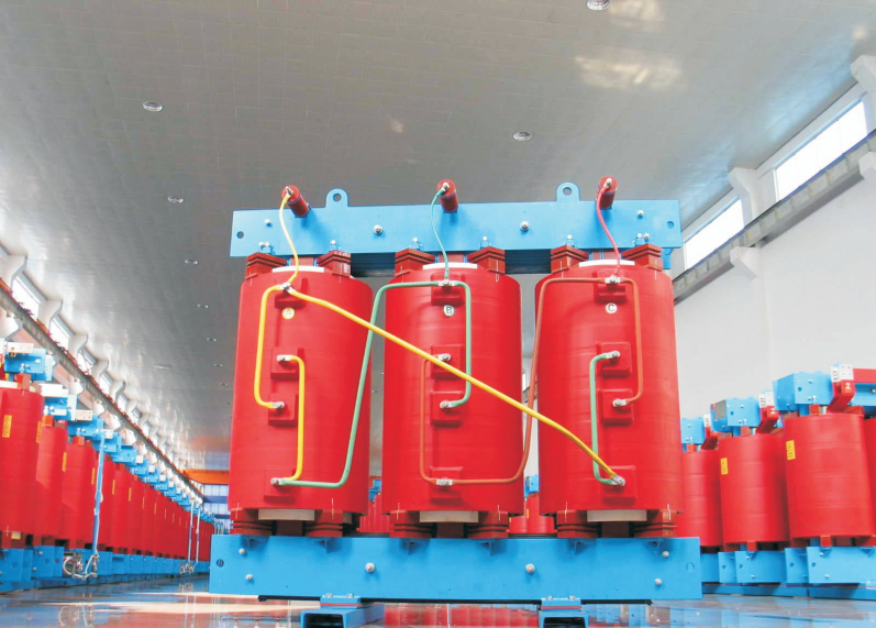
Dry-type cooling (AN/AF) eliminates oil leak risks and fire hazards, making them standard for indoor or highly regulated commercial environments, despite lower maximum ratings.
Smart transformer procurement evaluates not just the cooling class, but the auxiliary power consumption and mechanical failure risks (e.g., pumps, fans) introduced by forced-cooling designs.
You must first define the core business problem. Heat generation within electrical equipment scales non-linearly with the electrical load. Transformers produce heat through copper losses and iron losses. Iron losses remain relatively constant while the unit stays energized. However, copper losses scale with the square of the load current. A modest load increase can trigger a massive spike in internal temperatures. Buyers must solve for everyday baseline operation first. You must also account for peak summer ambient temperatures. Finally, you must plan for future capacity scaling without risking premature insulation failure.
Your baseline evaluation must align with strict industry standards. A solid transformer thermal design adheres to IEEE C57.12.00 or IEC 60076 frameworks. These standards mandate specific temperature rise limits. Most industrial units specify a 55°C or 65°C average winding rise over ambient. If you push temperatures past these limits, you destroy the internal paper insulation. Every excessive degree drastically shortens equipment lifespan.
You must also weigh long-term operational expenses against upfront capital expenses (CAPEX). A passive cooling design costs more initially. It requires a significantly larger physical transformer core and wider external radiators. However, it saves you heavily on auxiliary power consumption over decades. Forced cooling reduces the initial physical footprint. But it immediately shifts those savings into higher daily operational expenses and maintenance burdens.
Oil-immersed units dominate utility and heavy industrial sectors. Mineral oil serves as an exceptional insulator and heat transfer medium. Engineers categorize these setups based on how they circulate both the internal oil and the external air.
This mechanism relies purely on the thermosyphon effect and natural air convection. Hot oil rises toward the top of the tank. It then flows outward into external radiators. As ambient air cools the oil, it becomes denser and sinks. The cooled oil flows back into the bottom of the tank. ONAN features zero auxiliary moving parts. This grants it the highest reliability rating possible. It stands out as the best choice for remote locations. You should specify ONAN where you have ample footprint and low maintenance access.
ONAF adds mechanical fans to the exterior radiators. These fans activate to accelerate air dissipation across the cooling fins. This evaluation unlocks typically 15% to 33% more load capacity than a purely ONAN unit. You gain flexibility without increasing the core size. ONAF proves ideal for facilities anticipating future load growth. It also helps facilities manage peak seasonal electricity demands during hot summer months.
This mechanism uses dedicated pumps to force oil through the core and windings. It then pushes the fluid through massive external heat exchangers. You achieve maximum cooling density for very high-voltage or high-MVA units. However, a major risk constraint exists. ODAF introduces critical mechanical failure points. These pumps require constant condition monitoring. A pump failure demands immediate load shedding to prevent internal boiling.
These units utilize complex oil-to-water heat exchangers. This method proves highly specialized for niche environments. Hydroelectric plants and offshore platforms frequently deploy them. You achieve extreme thermal efficiency with OFWF. However, this design strictly requires a reliable, clean, and continuous water source to function.
Cooling Capabilities Summary Chart
Cooling Class | Primary Mechanism | Best Application Scenario | Maintenance Burden |
|---|---|---|---|
ONAN | Thermosyphon & Natural Convection | Remote substations, ample space | Very Low |
ONAF | Natural Oil + Forced Air Fans | Variable loads, seasonal peaks | Medium (Fan checks) |
ODAF | Pumped Oil + Forced Air Fans | High MVA, tight space constraints | High (Pump & Fan checks) |
OFWF | Pumped Oil + Forced Water | Offshore, hydroelectric facilities | Very High (Water chemistry) |
Certain environments strictly prohibit large volumes of combustible oil. Indoor commercial spaces require alternative technologies. Dry-type units solve these environmental constraints by using solid insulation and ambient air.
Air Natural evaluation represents the baseline for dry units. They demand the lowest maintenance overall. These units are inherently fire-resistant. AN serves as the default choice for indoor commercial buildings. Sensitive industrial manufacturing zones also rely heavily on them. However, they remain limited in their maximum MVA ratings compared to oil units.
Air Forced mechanisms add high-velocity fans beneath the coils. These fans push ambient air upward through internal winding channels. This setup temporarily boosts capacity by up to 30%. It perfectly handles transient peak loads during shift changes. Fans remain inactive during normal baseload operations to save energy.
A procurement reality check is essential here. Dry-type units inherently run hotter than oil alternatives. They also possess significantly less thermal inertia. Oil acts as a massive thermal sponge during sudden load spikes. Dry units lack this protective fluid buffer. This means they are far less forgiving of prolonged overloading. Therefore, implementing a robust transformer cooling system strategy is critical to preventing winding failures in dry units.
Selecting the ideal thermal management strategy goes beyond mere nameplate ratings. You must evaluate several physical and operational constraints before finalizing a purchase.
Footprint and Space Constraints: Forced cooling (ONAF/OFAF) allows for a noticeably smaller physical transformer. You achieve the same KVA rating compared to purely natural cooling (ONAN). This proves critical in urban retrofits.
Maintenance Burden and Accessibility: Moving parts like fans and pumps require periodic inspection. Technicians must handle bearing replacements and control circuit testing. You must ask if your facility has the personnel to support this routine.
Acoustic Noise Limits: Forced-air fans generate significant dB(A) noise levels. Buyers must carefully evaluate local zoning laws. Urban substations and indoor commercial deployments often mandate strict noise ceilings.
Environmental & Fire Safety Risks: Oil methods require extensive containment strategies. You must build concrete catch basins. You must also implement complex fire suppression planning. These requirements directly impact your overall civil engineering costs.
Engineers often focus entirely on upfront purchase prices. This narrow view obscures significant long-term operational costs. Forced-cooling mechanisms introduce hidden financial and mechanical risks.
Auxiliary power consumption represents a massive parasitic load. The electrical energy used to run cooling fans and pumps adds up quickly. This equipment operates continuously over a 30-year lifespan. Initial vendor bids rarely factor in this ongoing power drain. It drastically impacts your monthly operational costs. A passive unit might cost more to buy, but it uses zero parasitic power.
Redundancy requirements also complicate forced designs. If an ODAF pump fails, the unit loses thermal control fast. The transformer must immediately derate its output to prevent catastrophic failure. Smart buyers must evaluate N+1 fan and pump configurations. You should install three pumps if you strictly need two. This ensures you maintain full load capacity during a component failure. You must also link associated telemetry to your central control systems.
Harsh environmental conditions heavily penalize forced cooling. Fans in ONAF or AF systems suck in surrounding ambient air. If they operate in dusty, corrosive, or coastal environments, they suffer accelerated degradation. Saltwater spray destroys standard fan housings rapidly. You must specify advanced protective coatings for all external moving parts in these zones.
We recommend following a structured procurement process. Use this sequential logic to finalize your thermal design choices.
Baseline the Environment: Determine exactly where the unit will sit. Note whether it is an indoor or outdoor installation. Record your worst-case ambient temperature extremes. Finally, identify any strict environmental compliance needs that dictate dry versus oil technologies.
Plot the Load Profile: Analyze your facility's daily electrical draw. If you maintain a steady continuous baseload, heavily favor passive ONAN or AN systems. If you experience highly variable peaks, favor ONAF or AF. This handles temporary spikes without forcing you to oversize the heavy core.
Define Maintenance Maturity: Evaluate your internal workforce capabilities. If the installation site remains unmanned, weight passive cooling methods heavily. If maintenance budgets are historically low, avoid complex pump systems entirely.
Request Specific Bid Data: Do not accept generic proposals. Mandate that vendors provide guaranteed load capacities with cooling both active and inactive. Demand exact acoustic output metrics. Finally, require them to list the exact auxiliary power draw for all mechanical components.
Selecting a thermal management setup is not just a standard engineering checkbox. It represents a massive financial and operational commitment for your facility. Rushing this decision often leads to either crippled electrical capacity or excessive maintenance headaches. You must carefully balance upfront investments with expected operational realities.
Avoid evaluating these technologies in a vacuum. The most efficient thermal design is the one that perfectly aligns with your facility's specific load dynamics. It must respect your spatial constraints and environmental regulations. Above all, it must match your team's maintenance maturity over a 30-year lifecycle. Collaborate closely with vendors to ensure your final choice delivers both reliability and long-term value.
A: Yes. Adding cooling fans to an existing ONAN unit to convert it to ONAF is common practice. However, you can only do this if the radiators are originally designed to accept fans. Furthermore, the internal wiring must safely handle the newly increased MVA output.
A: Lifespan is tied directly to paper insulation health. For every 6°C to 8°C increase above the designed operating temperature, the insulation's useful life is halved. Adequate cooling systems preserve this thermal baseline and prevent premature degradation.
A: Nameplates often show dual ratings, such as 20/26.6 MVA. The first number reflects the unit's passive capacity using natural convection (ONAN). The second, higher number denotes its maximum safe capacity when all external forced-air fans are actively running (ONAF).
A: While the solid transformer core remains highly reliable, forced cooling introduces vulnerable moving parts. Mechanical pumps and fans have much shorter lifecycles (10 to 15 years) than the core itself (30+ years). These auxiliary components require proactive maintenance to prevent sudden capacity derating.