Views: 0 Author: Site Editor Publish Time: 2026-08-24 Origin: Site
Choosing a distribution transformer for an industrial facility is a system-design decision, not a catalogue comparison. The transformer must supply the real operating load while fitting the site voltage, installation environment, protection arrangement, fault-duty assumptions, maintenance model, and expansion plan. An oversized unit can add cost and operate inefficiently at very light load; an undersized or poorly matched unit can limit production, create unacceptable voltage drop, or reduce equipment life. This guide gives facility owners, engineers, and procurement teams a disciplined way to turn load information into a defensible transformer specification.
Start with measured or well-documented load data, including demand, diversity, motor starting, harmonics, and planned growth.
Select kVA from the facility’s actual operating profile, not simply by adding all nameplate ratings.
Confirm primary and secondary voltages, vector group, impedance, neutral arrangement, and protective coordination as a complete system.
Match transformer type and enclosure to indoor or outdoor location, fire strategy, environmental exposure, space, and maintenance capability.
Compare lifecycle consequences such as energy losses, downtime risk, access, and service rather than focusing only on purchase price.
An industrial site rarely has one steady load. It may have motors that start at different times, variable-speed drives, welding equipment, process heating, compressors, pumps, lighting, control loads, battery charging, and future production equipment. A useful selection process begins by creating a load schedule that records the equipment rating, normal operating demand, expected simultaneity, operating hours, power factor where known, motor-starting behavior, harmonic contribution, and planned additions.
Nameplate totals alone can be misleading. Some loads run only occasionally, while others operate continuously. A plant with several large motors may have modest steady demand but demanding starting events. A facility with power-electronic loads may need special attention to harmonic effects and thermal performance. A good load assessment uses measured interval data when the site already exists; for a new site, it uses process design information and conservative, documented assumptions that can be revisited at commissioning.
The calculation can be expressed in plain text as: transformer kVA = connected kW × demand factor / (power factor × planned loading factor). This is a planning relationship, not a substitute for an engineering study. Demand factor, power factor, and the planned loading factor must be chosen from the actual facility profile. The resulting preliminary value should then be tested against motor starting, harmonics, ambient conditions, required redundancy, and future load growth.
Separate the facility load into groups that behave differently. Base process load, intermittent process load, motor loads, non-linear loads, essential loads, building services, and future loads often deserve separate rows. Identify the production conditions that create the highest simultaneous demand. An idle-shift average may be useful for energy planning, but it should not determine the transformer size for a full production shift.
Ask operating teams practical questions. Which motors start across the line and which use soft starters or drives? Can starts be sequenced? Does a furnace or compressor cycle with another major load? Is a large future production line already approved? Is the facility expected to grow through a second transformer or a single larger unit? These answers are more valuable than an arbitrary spare-capacity percentage.
Also consider how the utility supply and downstream system respond to load changes. Voltage dip during starting, available fault level, protective device settings, and cable lengths influence whether a nominally adequate transformer performs acceptably. The transformer selection should be coordinated with switchgear, conductors, protection, grounding, and power-quality mitigation instead of treated as an isolated purchase.
Once a preliminary rating is identified, translate it into a complete electrical specification. The primary voltage must match the available supply. The secondary voltage must match the utilization system and equipment. Frequency, phase arrangement, tap requirements, vector group, neutral configuration, impedance, insulation level, and connection arrangement may all matter. The correct values are not universal; they follow the local grid, facility distribution design, and equipment requirements.
Transformer impedance is a good example. It influences voltage regulation and short-circuit behavior, so it affects both normal operation and protective-device coordination. Changing impedance to solve one issue can create another. Similarly, a neutral arrangement influences grounding and protection design. These choices should be reviewed by the responsible electrical engineer with current system data rather than copied from a previous project.
Selection item | Question to resolve | Why it matters | Evidence to retain |
|---|---|---|---|
Rating and loading | What is the peak demand, duty cycle, and expansion case? | Determines thermal margin and usable capacity | Load schedule and assumptions |
Primary and secondary voltage | What is available upstream and required downstream? | Prevents incompatible equipment interfaces | Single-line diagram and utility data |
Impedance and fault duty | How will the transformer affect fault current and voltage performance? | Supports coordination and equipment ratings | Short-circuit and protection study |
Winding and neutral arrangement | What grounding and distribution scheme is used? | Influences protection and downstream operation | Grounding and protection design |
Losses and efficiency | How many hours and at what load will it run? | Affects operating cost over the asset life | Loss data and load profile |
Environment and installation | Indoor, outdoor, corrosive, hot, dusty, or restricted site? | Determines type, enclosure, clearances, and maintenance | Site survey and installation drawing |
Distribution transformer selection is closely tied to where the unit will live. An indoor electrical room may prioritize fire strategy, ventilation, access, noise, clearance, and building interfaces. An outdoor installation may prioritize weather protection, temperature range, contamination, security, corrosion, and maintainable access. A compact industrial site may favor an integrated approach that reduces field interfaces, while a larger site may require separate equipment to suit redundancy or staged expansion.
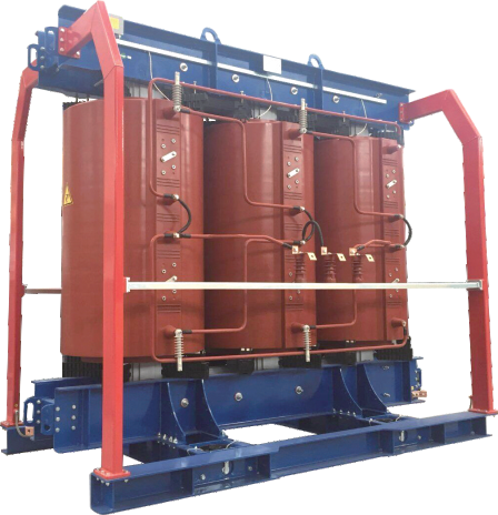
The term “dry type” and “oil immersed” should not be used as shorthand for good and bad. Both can be appropriate in the right application. Dry-type designs are often considered when indoor installation, fire considerations, or reduced fluid-handling requirements are important. Oil-immersed designs can be a strong solution where their installation, containment, maintenance, and environmental considerations are properly addressed. The final choice should be based on risk assessment and site requirements, not a generic preference.
For sites that benefit from packaged distribution, 4E’s prefabricated transformer solution describes an arrangement that integrates high-voltage equipment, a transformer, and low-voltage equipment in functional compartments. A project team should still verify that its voltage, protection, enclosure, environmental, and access requirements are met before selecting a packaged solution.
Motor behavior often changes the practical transformer requirement. A large motor start can cause a temporary voltage dip that affects other loads, controls, and process stability. The severity depends on the motor-starting method, system impedance, transformer characteristics, cable run, and simultaneous loading. A facility may reduce the issue by sequencing starts, using appropriate starting equipment, revising the distribution architecture, or selecting a transformer specification that suits the duty. The answer should come from a study, not a rule of thumb.
Non-linear loads also deserve attention. Variable-speed drives, rectifiers, UPS systems, welding equipment, and some electronic loads can introduce harmonic current. Harmonics can increase heating and affect voltage waveform. The design team should quantify the likely load spectrum, confirm the transformer manufacturer’s guidance for the intended duty, and coordinate mitigation with the distribution design. It is not enough to assume that a nominal kVA rating covers every waveform.
Power factor correction can alter the current and demand profile, but it should be designed with the facility’s harmonics and switching behavior in mind. Treat power quality as part of the load model from the beginning. It is much easier to reserve space, define monitoring points, and coordinate equipment at design stage than to retrofit around a disruptive operating problem.
The desired service continuity may lead to a different solution than simple peak-load sizing. A site with a tolerable shutdown window may accept one transformer with planned maintenance. A facility with a critical process may need sectionalization, a spare strategy, a second transformer, or a dedicated supply for essential loads. Redundancy is a business decision supported by electrical analysis: it depends on the cost of downtime, the ability to shed load, repair lead time, and the nature of the process.
Growth should be expressed as specific scenarios. Instead of adding an arbitrary margin, list the approved expansion loads, their timing, and their electrical behavior. Compare options such as installing a larger transformer now, allowing physical and electrical space for a second transformer, or using a modular packaged arrangement. Include switching, protection, cable, civil, and control implications. The lowest first cost can become expensive if the next expansion requires a major shutdown and reconstruction.
The purchase price is only one part of transformer ownership. Review no-load and load losses, expected loading profile, maintenance, installation civil works, enclosure needs, fire or containment measures, access, spare strategy, service support, monitoring, and downtime exposure. A unit with a lower purchase price but higher losses can be more expensive over a long operating period. Conversely, an unusually low-loss choice may not provide value if it is incorrectly sized for the duty.
Ask suppliers for comparable data on the same basis: rating, voltage, impedance, cooling or insulation design, specified losses, accessories, enclosure, test documentation, delivery scope, and exclusions. A comparison becomes unreliable when one quotation includes protection interfaces or accessories that another excludes. Technical and commercial teams should use one controlled comparison sheet so that deviations are visible.
4E’s transformer product range can be a starting point for discussing transformer and compact-substation configurations. The final specification should be checked against the project single-line diagram and the actual facility duty.
A strong request for quotation tells potential suppliers what the transformer must do and how compliance will be shown. Include the electrical rating and voltages, frequency, installation type, ambient and site conditions, required taps, impedance expectations, winding and neutral arrangement, insulation or cooling requirements, enclosure needs, accessories, monitoring, terminals, test requirements, documentation, packing, commissioning support, and applicable standards or customer specifications.
State the interfaces. Identify the incoming and outgoing cable or bus connections, space constraints, lifting route, foundation or plinth, grounding point, protection devices, remote monitoring needs, and maintenance clearance. Share the current single-line diagram and site data under the project’s document-control process. Ambiguity at quotation stage usually returns as a variation, delay, or field modification.
Factory acceptance testing and site acceptance should also be planned. The factory documentation should identify the supplied configuration and demonstrate the agreed tests. On site, inspection should confirm that the delivered unit, accessories, connections, protection settings, grounding, and installation conditions match the design. Energization should follow the project’s approved procedures and safety rules.
The best distribution transformer is the one that fits the facility’s real load, system architecture, environment, reliability objective, and future plan. Begin with measured or defensible load assumptions, then coordinate rating, voltage, impedance, protection, installation type, and lifecycle implications. Avoid a purely catalogue-led decision. When the transformer is specified as part of the industrial power distribution system, procurement becomes clearer and commissioning becomes more predictable.
Start with a load schedule, apply justified demand and diversity assumptions, account for power factor, then test the preliminary result against starting duty, harmonics, ambient conditions, and planned growth. Have the final selection reviewed with the facility system study.
Add capacity for defined future loads, uncertainty that cannot yet be resolved, or a reliability strategy. An arbitrary margin can add cost without solving the actual expansion or continuity requirement.
No. Nameplates do not show simultaneous operation, motor-starting sequence, operating duty, harmonic content, or future growth. Those factors can materially change the selection.
Dry-type designs are often considered for indoor sites or where fire strategy, fluid handling, and maintenance conditions make them suitable. The choice must still consider load, ventilation, environment, noise, access, and project requirements.
Impedance affects both voltage behavior under load and available fault current. It must coordinate with the facility’s protection, conductors, switchgear, and motor-starting requirements.
Provide the single-line diagram, primary and secondary voltages, rating target, installation environment, load profile, protection information, required accessories, standards, site constraints, and future expansion assumptions. This helps suppliers return technically comparable proposals.