Views: 0 Author: Site Editor Publish Time: 2026-07-06 Origin: Site
Power demand inside large facilities is rarely concentrated in one place. It moves through substations, transformers, production lines, HVAC systems, lighting networks, backup power equipment, and auxiliary circuits, often across long routes with different thermal and mechanical conditions. A cable chosen only by size or price can create voltage drop, overheating, premature aging, or maintenance problems later.
Reliable High-Capacity Power Cables help facilities distribute heavy electrical loads safely and efficiently when they are matched to real operating conditions. Choosing the right cable means looking at load demand, voltage level, route length, insulation, sheath protection, standards, and installation quality together.
Cable planning should begin with a clear map of the facility’s electrical demand. Engineers need to identify incoming power points, transformer rooms, distribution boards, motor control centers, heavy machinery zones, HVAC equipment, lighting circuits, emergency power systems, and future expansion areas. This load map helps separate backbone power routes from final distribution circuits, so each cable is selected for the job it actually performs. Without this step, a project can easily overspend on unnecessary capacity in one area while leaving another route exposed to overheating or voltage instability.
Actual operating conditions matter more than nameplate ratings alone. A production line with motors, drives, pumps, compressors, and conveyors may create high starting currents or fluctuating loads that affect cable sizing. Long cable routes can increase voltage drop, while crowded trays, high ambient temperature, or enclosed ducts can reduce heat dissipation. Harmonics from variable-frequency drives and nonlinear loads may also increase thermal stress. For large facilities, High-Capacity Power Cables should be chosen only after continuous load, peak demand, route length, derating factors, and expansion margin have been reviewed together.
Voltage level should match the role of the cable within the facility. High-voltage cables are typically used for backbone transmission, grid connections, substations, power stations, industrial parks, underground urban networks, and renewable-energy transmission routes. Medium-voltage cables often serve plant-wide distribution, transformer connections, and high-load equipment zones. Low-voltage cables are used closer to the final load, such as equipment connections, lighting, office systems, appliances, and control circuits.
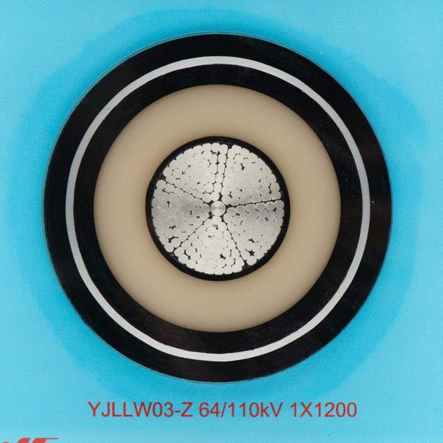
This distinction prevents one of the most common selection mistakes: using a cable because it is available rather than because it fits the electrical duty. 4E’s high-voltage XLPE insulated power cable family covers 66kV to 500kV applications, with voltage levels such as 66kV, 110kV, 132kV, 220kV, 330kV, 400kV, and 500kV. These cables are suitable for underground power transmission, tunnel installations, submarine cable links, grid interconnections, and long-distance power links. Low-voltage flexible cables, by contrast, should remain in properly rated final or auxiliary circuits rather than being treated as heavy-duty feeders.
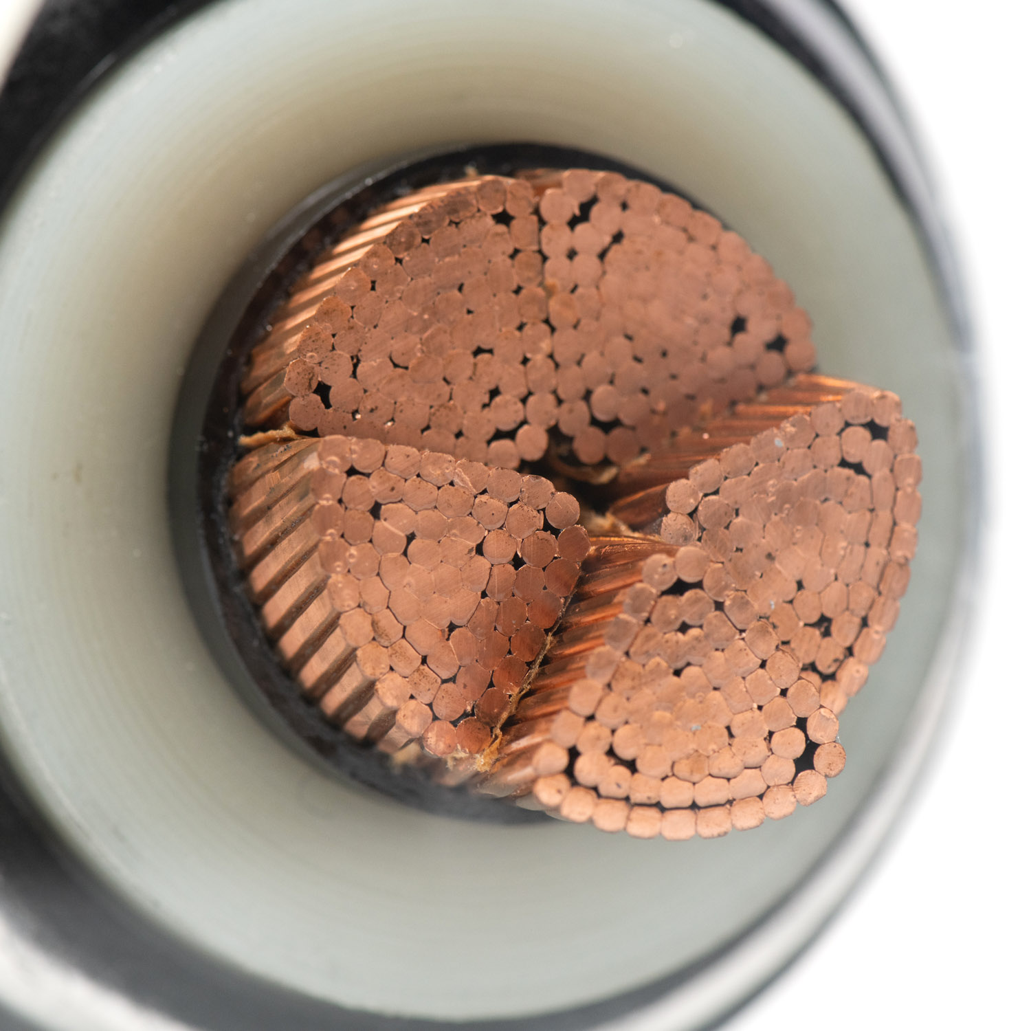
Conductor selection has a direct impact on energy loss, heat generation, cable size, weight, and installation handling. Copper offers higher conductivity and can support compact cable designs where space is limited or high performance is required. Aluminum is lighter and often more economical for large-scale routes, especially where conductor weight and project cost are major considerations. Neither material is automatically better in every situation; the better choice depends on current-carrying requirements, installation method, termination quality, budget, and mechanical demands.
In a large facility, conductor decisions influence both upfront and long-term performance. A conductor with excessive resistance can increase heat and voltage drop over long routes. That extra heat may accelerate insulation aging and reduce service reliability. On the other hand, selecting a larger or more expensive conductor than necessary can raise procurement and installation costs without improving system value. 4E’s high-voltage XLPE cable series includes both copper and aluminum conductor options, supporting different project requirements for conductivity, weight, installation handling, and cost control.
Insulation quality is central to the safety and efficiency of High-Capacity Power Cables. In demanding facilities, insulation must withstand electrical stress, operating heat, fault conditions, and long-term aging. XLPE insulation is widely used in high-voltage and demanding power-distribution environments because it combines strong dielectric performance with thermal stability. Good insulation also helps reduce leakage risk and supports reliable operation under sustained electrical load.
For backbone routes and major feeders, thermal performance deserves close attention. Cables may run near full load for long periods, and short-circuit events can create extreme temporary temperatures. 4E’s high-voltage XLPE cable uses XLPE insulation for dielectric performance, thermal stability, aging resistance, 90°C normal operating temperature, and 250°C short-circuit temperature. These characteristics are useful when engineers compare cable constructions for high-load zones where heat control and insulation integrity cannot be compromised.
The outer layers of a cable protect the electrical core from the real conditions of the facility. Underground routes, cable trenches, tunnels, basements, outdoor transitions, wet areas, and corrosive environments all place different demands on the sheath system. A cable that performs well in a dry indoor route may not last in a damp tunnel or chemical-exposure area. Sheath selection should therefore be connected to route planning from the start.
4E’s high-voltage cable range includes PVC or PE outer sheath options, corrugated aluminum sheath structures, and optional longitudinal water-resistant designs. Corrugated aluminum sheath enhances mechanical protection and water tightness, while longitudinal water-resistant configurations are suitable for wet, submerged, underground, submarine, and wet tunnel environments. For large facilities, this means sheath selection is not a cosmetic detail. It is part of the service-life strategy, especially where moisture, abrasion, impact, UV exposure, or chemicals may shorten cable life.
The highest-capacity cable routes are usually found at the utility intake, substation connections, transformer links, renewable-energy tie-ins, and long-distance internal transmission paths. These routes carry large amounts of power and must be designed with careful attention to voltage rating, fault current, route length, sheath protection, grounding, accessories, and testing. A failure in this section can affect the entire facility, so selection should focus on system reliability rather than only purchase price.
High-voltage XLPE cables are a logical fit for this part of the network when the project requires large-scale transmission capacity. 4E’s 66–500kV XLPE insulated cables are suitable for high-voltage and extra-high-voltage transmission, including power grids, underground power transmission, tunnel routes, grid interconnections, offshore wind farm export cables, and long-distance power links. In a large facility, these cables may form the backbone that connects the external power supply to internal distribution infrastructure.
Production areas introduce a different set of cable stresses. Motors, drives, pumps, compressors, conveyors, cranes, and large building-service equipment may create heat, vibration, starting currents, and regular maintenance activity around cable routes. Cable trays can become crowded as systems expand, and enclosed routes may limit heat dissipation. Mechanical protection becomes especially important where forklifts, tools, machinery movement, or maintenance access could expose cables to impact or abrasion.
This section of a facility does not simply need “large cables.” It needs cables selected for operating conditions. Engineers should check current demand, installation spacing, bending radius, tray loading, ambient temperature, and possible exposure to oils, water, dust, or chemicals. Route protection, cable supports, labels, and accessible maintenance paths can be just as important as electrical sizing. A well-matched cable system helps reduce downtime because it accounts for both the electrical load and the physical environment around the equipment.
Overheating is one of the most serious risks in facility power distribution. Undersized cables, long routes, crowded trays, high ambient temperature, poor ventilation, and incorrect derating can all push a cable beyond its intended thermal condition. Once heat builds up, insulation aging accelerates, resistance losses increase, and equipment may experience unstable voltage. In severe cases, the result can be nuisance trips, unplanned downtime, damaged equipment, or fire risk.
Voltage drop deserves the same level of attention. A cable may carry the current safely but still deliver poor performance if the route is too long or the conductor selection is not suitable. Motors may run less efficiently, sensitive equipment may behave unpredictably, and operators may experience repeated system faults that are difficult to diagnose. High-Capacity Power Cables should therefore be selected with both ampacity and voltage drop in mind, especially in large plants, industrial parks, and infrastructure facilities.
Before confirming cable capacity, engineers should check:
● Load current and peak demand
● Cable route length
● Voltage drop calculation
● Ambient temperature
● Tray, conduit, or duct derating
● Future expansion margin
Moisture and mechanical damage often create failures that could have been prevented through better route design. Cable trenches, underground ducts, tunnels, basements, outdoor transitions, and production floors may expose cables to water ingress, abrasion, impact, chemical exposure, pulling tension, UV exposure, or repeated movement around maintenance zones. A cable chosen only by voltage and current rating may not survive these conditions for its intended service life.
Sheath material and route protection should be selected together. A PE sheath may be preferable where chemical resistance and moisture durability are priorities, while PVC may fit routes where flame retardancy and general mechanical protection are more important. Longitudinal water-resistant designs can add another level of protection in damp or wet routes. Cable bends, supports, glands, and entry points also need careful control because route stress can damage a cable long before the conductor reaches its electrical limit.
Procurement should confirm more than the cable name and price. Large-facility projects need documentation covering voltage rating, conductor material, cross-section, insulation type, sheath material, water-blocking structure, fire behavior, bending radius, installation temperature, test data, and accessory compatibility. These details help prevent mismatches between design assumptions and delivered cable performance. They also support acceptance testing and long-term maintenance records.
Standards verification is especially important for high-voltage and extra-high-voltage routes. 4E’s high-voltage XLPE cable is designed around IEC 60840 for extruded insulation cables and accessories above 30kV up to 150kV, and IEC 62067 for extruded insulation cables above 150kV up to 500kV. For low-voltage flexible wiring, documentation should confirm the exact rating and intended use. The H05VVH2-F cable features a 300/500V rated voltage, 2000V test voltage for five minutes, 70°C maximum conductor operating temperature, 160°C short-circuit temperature, and self-extinguishing flame performance according to IEC 60332-1.
Cable reliability depends heavily on installation quality. Joints, terminations, glands, grounding, pulling methods, supports, labeling, and final testing can all affect performance. Even a well-designed cable may fail early if it is pulled with excessive force, bent beyond its permitted radius, poorly terminated, or installed in an unsuitable route. For high-load systems, installation should be treated as part of the cable specification rather than a separate afterthought.
Checkpoint | Why It Matters |
Load and voltage confirmed | Prevents under-capacity or unnecessary oversizing |
Route and environment reviewed | Helps match sheath, water resistance, and mechanical protection |
Standards verified | Reduces compliance and acceptance risk |
Accessories planned | Improves joint and termination reliability |
Testing process defined | Supports safe energization and long-term operation |
Selecting High-Capacity Power Cables for large facilities is a practical engineering decision, not just a specification exercise. Load demand, voltage level, route length, insulation performance, sheath protection, standards, and installation quality all affect how safely and efficiently power moves through the facility.
East Energy Electrical Engineering Co., Ltd. supports this process with high-voltage, medium-voltage, and low-voltage power cables, along with cable accessories, installation, commissioning, and acceptance services. When cable selection is matched to real site conditions, facilities can reduce losses, control heat, improve reliability, and prepare for future expansion.
A: They carry substantial electrical loads across substations, transformers, main feeders, production areas, and auxiliary systems while supporting safe, efficient power distribution.
A: Engineers check voltage level, load current, route length, voltage drop, installation conditions, conductor material, insulation type, and long-term reliability needs.
A: Excessive voltage drop can reduce motor efficiency, cause unstable equipment operation, increase heat, and lead to damage or circuit breaker trips.
A: No. High-voltage cables suit backbone transmission and long-distance distribution, while low-voltage cables are used closer to final equipment, lighting, and auxiliary circuits.
A: Insulation must withstand normal and abnormal voltage stress, helping prevent leakage, breakdown, overheating, and premature failure in demanding electrical systems.
A: Confirm load data, voltage rating, route environment, conductor size, sheath protection, bending radius, accessories, grounding, and testing requirements before installation begins.