Views: 0 Author: Site Editor Publish Time: 2026-09-17 Origin: Site
Sizing a transformer for standard AC distribution is straightforward. However, sizing one for non-linear, high-current DC applications presents a highly specialized engineering challenge. Engineers must account for complex electrical behaviors rarely seen in conventional power grids. Industrial DC processes like heavy electrolysis, smelting operations, and large variable speed drives generate severe harmonic distortion. They also create dangerous DC voltage bias and highly dynamic load profiles.
These harsh electrical conditions quickly degrade standard distribution transformers. Overlooking these factors leads to sudden insulation failures and costly facility downtime. This guide outlines the essential engineering frameworks and thermal considerations needed for long-term reliability. You will learn the exact compliance standards required to safely specify a rectifier transformer for industrial DC loads. We provide actionable insights to ensure maximum process uptime and prevent catastrophic thermal failures across your heavy industrial operations.
Harmonic Mitigation is Mandatory: Accurate selection requires calculating the K-factor and accounting for eddy current losses driven by specific rectifier topologies (6-pulse, 12-pulse, or 24-pulse).
Derating is Not a Guessing Game: Capacity must be strictly aligned with IEEE C57.18.10 or IEC 61378-1 standards to prevent insulation degradation.
Topology Dictates Design: The configuration of the industrial DC power supply directly determines necessary winding phase shifts and coupling requirements.
Standard power transformers operate smoothly under clean, linear 50Hz or 60Hz sine waves. When you introduce industrial rectifiers into the circuit, the electrical landscape changes dramatically. Rectifiers draw current in abrupt, non-linear pulses. This fundamentally alters how the transformer must manage heat and electromagnetic stress.
Non-linear loads create intense harmonic currents. These high-frequency currents circulate through the transformer windings alongside the fundamental frequency. Harmonics do not contribute to useful work. Instead, they exponentially increase eddy current losses inside the core and copper windings. Standard transformers cannot dissipate this rapidly accumulating heat. The internal temperature quickly exceeds the thermal limits of basic insulation, leading to premature winding failure. You must specify specialized cooling channels and customized conductor geometries to survive this harmonic heat.
Industrial rectifiers often leak a small amount of direct current back into the AC side of the circuit. We call this phenomenon DC bias. DC bias causes asymmetrical magnetization within the transformer core. It forces the core to saturate much earlier during one half-cycle of the AC waveform. Core saturation drastically increases magnetizing current. It also generates loud acoustic noise, violent vibration, and runaway thermal spikes. A dedicated transformer for rectifier system utilizes specialized core joint designs and lower flux densities to safely absorb this DC bias without saturating.
Heavy DC processes experience frequent short-circuits. Think of an electric arc furnace striking a heavy charge. These events send massive high-current transients back through the system. Standard AC transformers lack the heavy-duty mechanical bracing required to survive these repeated shocks. The electromagnetic forces generated during these transients can literally tear standard windings apart. Rectifier units feature heavily reinforced clamping structures and epoxy-bonded winding blocks to maintain structural integrity during extreme fault conditions.
Selecting the right equipment requires rigorous mathematical modeling. You cannot simply look at the megawatt rating of your load and pick a matching kVA transformer. You must evaluate the load profile, harmonic spectrum, and winding architecture simultaneously.
The first step involves defining the exact operational duty cycle. You must differentiate between base continuous loads and transient overload demands. For example, heavy traction railway systems utilize specific duty classes (Class I, II, III, and IV). Each class dictates how long the equipment must survive extreme overloads.
To calculate the proper capacity, follow this sequence:
Determine the absolute continuous base load in kilowatts required by the DC process.
Identify the maximum overload percentage and its exact duration.
Calculate the fundamental kVA needed to support this power draw.
Apply the calculated harmonic spectrum to find the harmonic-adjusted equivalent kVA.
This equivalent kVA rating represents the true thermal capability your transformer must possess.
The pulse count of your rectifier topology dictates the transformer's winding complexity. Higher pulse configurations effectively reduce Total Harmonic Distortion (THD) on the primary grid. However, they demand highly complex secondary winding arrangements.
A basic 6-pulse system requires a standard primary and secondary winding. A 12-pulse system requires two secondary windings. One secondary must connect in a wye configuration, while the other connects in a delta configuration. This creates a mandatory 30-degree phase shift between the two outputs. This phase shift cancels out the most damaging 5th and 7th order harmonics. Upgrading to 24-pulse systems requires complex zigzag windings to achieve 15-degree phase shifts. You must select the correct vector group, such as Dy11d0, to guarantee accurate phase alignment.
Heat destroys insulation. Proper rectifier transformer selection relies heavily on accurate thermal derating. Engineers use the K-factor or Harmonic Factor (HF) to quantify the extra heating effect of harmonic currents. The K-factor directly influences how much you must oversize the transformer's cooling capacity.
You must select robust insulation systems capable of surviving these elevated temperatures. Class F (155°C) and Class H (180°C) insulation materials remain the industry standard for these high-stress environments. Never use standard Class B materials for heavy non-linear applications.
Impedance dictates how the transformer responds to load changes and short circuits. You must balance two competing priorities here. Low impedance provides excellent voltage regulation, keeping the DC output stable. High impedance limits destructive short-circuit currents during a fault.
When engineering multi-pulse systems, equal impedance between all secondary windings is absolutely critical. If the wye winding has a different impedance than the delta winding, the rectifiers will not share the current equally. This imbalance forces one winding to overheat while the other remains underutilized.
Different industries impose radically different demands on their power infrastructure. You must tailor the transformer design to the specific realities of the operational environment.
Aluminum smelting and chlorine electrolysis facilities operate 24 hours a day, 365 days a year. They draw ultra-high continuous currents. Any interruption ruins the batch and damages the production equipment. The primary success criterion here is extreme reliability under massive continuous load.
These processes also require incredibly fine voltage regulation as the chemical bath resistance changes. Engineers typically integrate heavy-duty On-Load Tap Changers (OLTC) directly into the transformer. This allows operators to adjust the voltage precisely without shutting down the industrial DC power supply.
Railway substations present a completely different challenge. Trains pull massive amounts of current as they accelerate. Then, they suddenly coast or brake, dropping the load to near zero. This creates highly dynamic, erratic load profiles.
Transformers in these applications face frequent, severe overloads. They also endure high mechanical shock from rapid current fluctuations. Success requires heavy structural bracing and advanced thermal management to dissipate sudden heat spikes before the next train arrives.
Large mining conveyors and heavy industrial pumps rely on massive Variable Speed Drives. These facilities often operate in confined spaces or deep underground. A compact footprint becomes a major design constraint. Engineers frequently deploy 18-pulse or 24-pulse multi-winding designs for these VSDs. These high-pulse setups inherently cancel harmonics. This allows mining operators to meet strict IEEE 519 grid harmonic limits without installing bulky external harmonic filter banks.
Dissipating heat effectively determines the lifespan of your equipment. You must match the cooling technology to the physical environment and the available facility infrastructure.
You must carefully evaluate the installation environment before selecting the core technology.
Dry-type cast resin transformers offer exceptional safety. They use no flammable liquids. This makes them ideal for indoor installations, tight VSD cabinets, and strict fire-restricted zones. However, if you install them in dusty mining environments, you must specify robust IP-rated enclosures to prevent conductive dust from bridging the exposed coils.
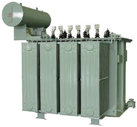
Liquid-filled transformers remain mandatory for ultra-high kVA applications, such as large smelting operations. Liquids like mineral oil, silicone, or synthetic esters provide superior thermal dissipation. They can absorb extreme continuous loads far better than dry-type units. They typically sit outdoors due to space and fire safety requirements.
Cooling Method | Description | Best Application Scenario | Maintenance Requirement |
|---|---|---|---|
ONAN (Oil Natural Air Natural) | Relies on natural convection of oil and ambient air. | Standard outdoor installations with moderate continuous loads. | Low. No moving parts. |
ONAF (Oil Natural Air Forced) | Uses cooling fans to push air across the radiators. | Systems requiring extra peak-load capacity during summer months. | Moderate. Fan motors require inspection. |
OFWF (Oil Forced Water Forced) | Uses pumps to move oil through a dedicated water heat exchanger. | Confined indoor smelting facilities with high-capacity chilled water loops. | High. Requires water quality management and pump maintenance. |
You must carefully plan how the transformer connects to the rectifier cabinet. Heavy copper busbars transmit thousands of amps. These busbars cannot easily bend around obstacles. You must specify exact termination locations during the design phase. Determine whether the equipment requires top, bottom, or side terminations. Perfect busbar alignment between the transformer and the rectifier cabinet minimizes resistance, reduces installation time, and prevents mechanical stress on the connection points.
Verifying performance before the equipment ships is the only way to guarantee field reliability. Never accept standard AC transformer test reports for heavy DC applications.
You must verify strict adherence to international standards. In North America, IEEE C57.18.10 outlines the exact practices for semiconductor power rectifier transformers. Globally, IEC 61378-1 governs these designs. These standards dictate specific safety margins, acceptable temperature rises, and mandatory construction techniques. Enforcing these standards ensures the manufacturer understands the severe nature of non-linear loads.
Standard routine tests will not uncover harmonic vulnerabilities. You must demand specialized testing protocols during the Factory Acceptance Test.
Harmonic Temperature Rise Tests: The manufacturer must simulate the actual harmonic current spectrum. They must prove the transformer stays within its temperature class while processing simulated non-linear loads.
Short-Circuit Withstand Verification: The design must mathematically or physically demonstrate it can survive maximum fault currents without mechanical deformation.
Applied and Induced Voltage Tests: These tests push the insulation system beyond normal limits. They verify the dielectric strength can handle transient voltage spikes generated by rectifier switching actions.
Selecting a rectifier transformer requires far more effort than sizing standard distribution equipment. You must move past basic kVA ratings and deeply analyze the harmonic profile of your process. Understanding your specific duty cycles and rectifier pulse counts will dictate the internal architecture of the transformer. Ignoring these factors guarantees premature thermal degradation and operational failure.
To ensure success, finalize your exact rectifier topology and harmonic spectrum first. Do not guess these parameters. Once you define the load, engage directly with a specialized transformer manufacturer. Provide them with your complete load profile, environmental constraints, and duty cycle specifications. This proactive engineering approach guarantees long-term reliability and safeguards your critical industrial processes.
A: Derating relies on calculating the K-factor in the US, or Factor K in Europe. This mathematical formula weights the harmonic currents based on their specific frequencies. It determines the exact amount of additional heat generated by eddy current losses. You then use this factor to correctly oversize the transformer's thermal capacity.
A: Rectifier transformers utilize heavier copper or aluminum conductors. They feature specialized phase-shifting winding geometries and heavily reinforced core bracing. These upgrades allow them to safely handle harsh DC harmonics, DC voltage bias, and frequent high-current transient overloads without overheating or breaking down physically.
A: Higher pulse numbers actively cancel out lower-order harmonics right at the winding level. For example, a 12-pulse system eliminates the destructive 5th and 7th harmonics. This prevents serious harmonic pollution from reaching the main grid, satisfies strict IEEE 519 compliance rules, and removes the need for large, expensive external harmonic filters.
A: Yes. Manufacturers typically install an electrostatic shield between the primary and secondary windings. This grounded shield significantly attenuates high-frequency common-mode noise. It also blocks dangerous transient voltage spikes generated by the rapid switching of rectifier diodes or thyristors, successfully protecting the upstream electrical grid.